

Figure 1 Figure 2


Figure 3

Figure 4

In Figure 2 you see the workers pouring water down the hole and Figure 3 shows water being poured on the drill bit. In the center of Figure 4 the crawler crane is maneuvering the winch towards the workers.
Another activity included two excavators moving rocks around. Some rocks were piled and others were spread around in a big hole. The excavators were located in the middle of the construction site. See Figures 5-9.
Figure 5

Figure 6


Figure 7
Figure 8

Figure 9
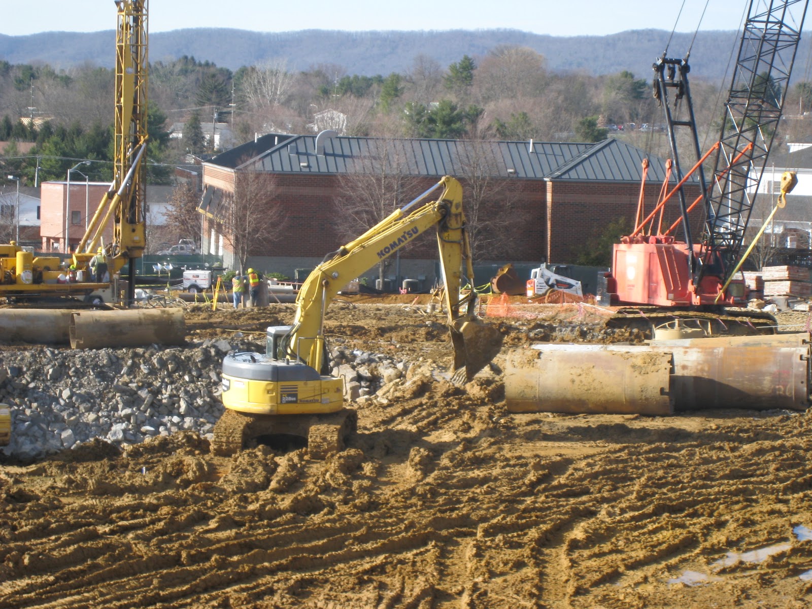
Figure 5, shows the location of the excavators. Figure 5, also shows the caisson drill in the background. Figure 6, shows the excavator extending towards the edge of the hole and pulling rocks and soil towards him. Figure 8, shows the other excavator moving around rocks, and Figure 9 shows the excavator turning around. The excavator in Figure 9 placed his bucket on the soil and waited for the other excavator to finish.
Another interesting activity that I observed was formwork and the installation of rebar cages. I want to show what I have learned in my Construction Principles class about reinforcing columns:
Figure 10

Figure 10 is how most columns are reinforced. At the bottom of the column you can see a lot of rebar. This is called lab splicing (Figure 12). In a previous class we discussed what the significance of reinforcing steal is. The reinforcing adds strength to concrete and prevents concrete from cracking. It is also important to know that a certain amount of concrete is needed to protect the steal from corroding. The tall reinforcing steal you see in Figure 10 is a reinforcing cage. It is very similar to the cages that is used in beams. See figure 11.
Figure 11.

Figure 12

Now, that I have explained some details I will show what I saw on site.
Figure 13. Figure 14


Figure 15

Figure 13, shows a fork lift maneuvering a reinforced cage. Figure 14, shows a worker guiding the cage into place and Figure 15 shows the cage set in place. Another thing to note in Figure 14 is the reinforcing along the formwork (Figure 14).
I want to show images of the formwork. In a previous blog, Pouring Concrete, I explained the basics of forming a pathway. Now, we have formwork for a wall. In the same Construction Principles class we learned about reinforcing a wall and then placing the formwork around it. In the picture below (showed to us in class) workers are busy with the second layer of formwork for the wall.
Figure 16

Below, are some pictures showing the first layer of the formwork. The images also show how the formwork was tied together.


I hope you are enjoying all the images and details.
Thank you for reading.
All the best,
Mic
I have to commend you for managing a construction project really well! The data you made with the basic information needed in the construction is proof enough that you consider even the smallest details. On a different note, what type of concrete did you use for the slab works?
ReplyDeleteLorenzo Hess